With decades of experience engineering and installing these systems, we can help you select from a full range of evaporator, condenser and self-contained unit sizes that will fit the most challenging of space conformity. Offering the most efficient systems, our soft-start technology that reduces by 60% the size generator required to start and run a system. Now you can enjoy the same reliability with more efficiency, less noise and a smaller foot print.
Factors That Determine the Type of System You Need
Size and layout of boat for calculating required system capacity.
Access for routing tubes/wires/hoses.
Location of furnishings.
Storage space to sacrifice.
Cost.
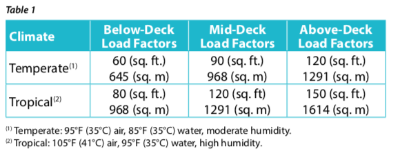
Step 1. Find the required capacity by dividing the vessel into three main load areas:
Below Deck. Cabins where the hull slopes inward toward the keel with minimal port lights and hatches.
Mid Deck. Areas on main deck with small or shaded windows.
Above Deck. Areas with large glass surfaces and direct sunlight.
Multiply the length and width of each cabin to be treated to determine the area in square feet or square meters. It is assumed the boat has average headroom of about 6.5 ft. (2 m) with an average amount of furniture. If one end of the cabin is narrower than the other, take your measurement in the middle.
Using Table 1, multiply the area of each cabin by the appropriate load factor to find the required air conditioner capacity. For example, if your boat is in a temperate climate and you are measuring in square feet, you would multiply your total below-deck area by 60, your mid- deck area by 90, and your above-deck area by 120.
Step 2. Taking into account the boat’s size and layout, determine the number of self-contained systems or air handlers needed.
Find out which cabins or areas will benefit best from a dedicated thermostat control, and which cabins can be served by ducting or a secondary air handler (where the only temperature control is an adjustable grille or fan-speed control).
Step 3. Taking into account the boat’s size and layout, determine the location of each self-contained system or air handler.
In addition to leaving enough room for plumbing and ducting, there must also be sufficient space in each installation location for servicing and/or removal of the unit.
A self-contained unit or air handler must have an open return-air path. However, the return-air grille does not need to be directly in front of the unit. In fact, the system will be less noisy if there is an indirect path for the return air to follow. Never install the unit in the bilge or engine room or where vapors from these areas could reach the unit.
A self-contained unit or air handler must be located so the discharge ducting can be routed to a high point in the cabin. Rotate the blower to create the most direct path for routing the discharge duct. Poor airflow may result from a ducting run of over 15 ft. (4.5 m) or a ducting run with many bends. Plan for the shortest possible ducting run while limiting the number of bends.
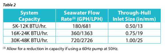
Step 4. Seawater Components. Use one pump of adequate capacity for all air conditioning systems on board. The basic rule is 180 gallons per hour (3 gpm) of water per ton of air conditioning (one ton is 12,000 BTU). If more than one system shares a common pump, you will also need a pump relay and manifold.
The BTU capacity in Table 2 shows recommended seawater flow rates and minimum inlet (through-hull) sizes.
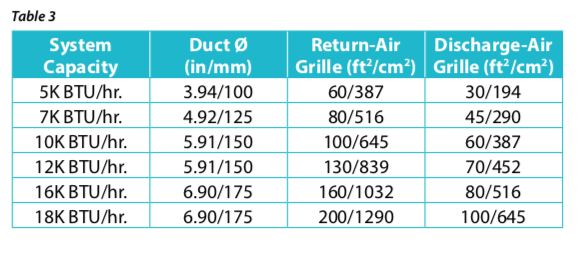
Step 5. Determine the proper duct diameter (0) and grille sizes for your air conditioning system. Use Table 3 to find the correct sizes, which are based on the system’s BTU capacity.
Other System Components
A complete air conditioning system requires controls, a seawater cooling system, an air-distribution system and electrical connections.
Controls
There are two types of controls: digital and mechanical (rotary-knob switch).
Seawater Cooling System
The seawater cooling system brings seawater into and through the system then discharges it overboard. It consists of an inlet through- hull fitting, seacock (water valve), strainer, pump, and overboard discharge fitting, all connected by hose or piping (see Figure 4).A/C
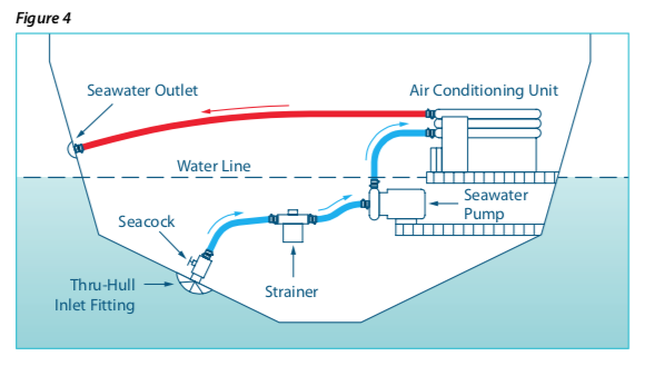
If multiple air conditioning units are served by a single seawater pump, then a pump relay and water manifold are required. A centrifugal seawater pump is recommended for efficient, quiet operation and long life. Centrifugal pumps are not self-priming and must be mounted below the water-line.
It is important that the seawater plumbing be self-draining, meaning that if the boat is lifted, all water in the piping will drain out. An air conditioning system plumbed this way will have no air locks which could disrupt the flow of seawater.
For shallow-draft boats where it is impossible to mount the pump below the water-line, a self-priming pump must be used.
Air-Distribution System
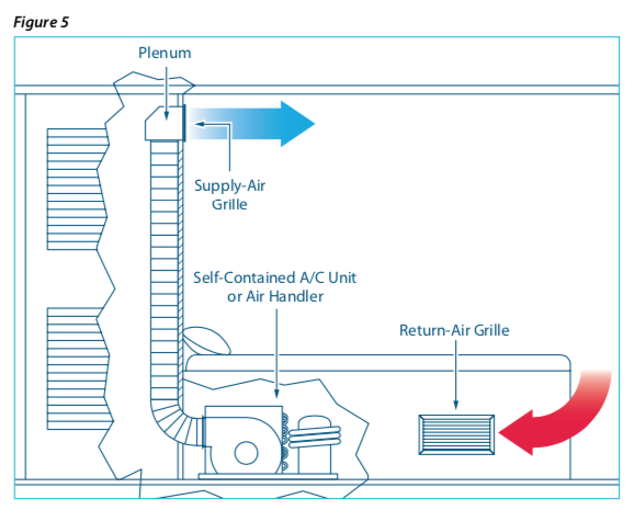
Cabin air is drawn into the self-contained unit or air handler through a return-air grille. It is then cooled (or warmed) and blown back into the cabin through a ducting system.
The supply-air grille should be positioned high in the cabin and away from the return-air grille to ensure good circulation. Plenums (transition boxes) can be installed in the ducting to split the air flow into multiple ducts to serve one or more cabins.
Figure 5 illustrates an air conditioning unit or air handler in cooling mode installed beneath a bunk. Ducting should be insulated to prevent secondary condensation. An air filter, located on the cooling unit or on the return-air grille, must be cleaned or replaced regularly.
Electrical Connections
Most Dometic air conditioning systems are available in three power configurations: 115V 60Hz, 230V 60Hz, and 220V-240V 50Hz. Larger systems are available with three-phase compressors. Some 60Hz units can run at 50Hz, but not all.
Please check the specification sheet or contact your Dometic dealer if you have a particular power requirement.
Wire sizing should be done per ABYC requirements. Selecting the circuit breaker for the system:
Using a Generator
If running on a generator, make sure that it can handle the large starting inrush current of the compressor. Use of a Dometic SmartStartTM is highly recommended to smooth out starter demand and ease strain on the generator.
Take the product specification sheets to your generator supplier and ask for their help.
2992 Overseas Highway
Marathon, Florida 33050